The elbow is the load-bearing joint during arm swing
Article information

Abstract
Background
Arm swing plays a role in gait by accommodating forward movement through trunk balance. This study evaluates the biomechanical characteristics of arm swing during gait.
Methods
The study performed computational musculoskeletal modeling based on motion tracking in 15 participants without musculoskeletal or gait disorder. A three-dimensional (3D) motion tracking system using three Azure Kinect (Microsoft) modules was used to obtain information in the 3D location of shoulder and elbow joints. Computational modeling using AnyBody Modeling System was performed to calculate the joint moment and range of motion (ROM) during arm swing.
Results
Mean ROM of the dominant elbow was 29.7°±10.2° and 14.2°±3.2° in flexion–extension and pronation–supination, respectively. Mean joint moment of the dominant elbow was 56.4±12.7 Nm, 25.6±5.2 Nm, and 19.8±4.6 Nm in flexion–extension, rotation, and abduction–adduction, respectively.
Conclusions
The elbow bears the load created by gravity and muscle contracture in dynamic arm swing movement.
Level of evidence
Level IV.
INTRODUCTION
The upper limbs are not weight-bearing because humans walk on the two lower limbs. The assertion that the elbow is not a weight-bearing joint has been commonly accepted compared with the analogous tetrapod joint. However, the elbow joint is not completely free from load. Although precise determination of joint contact loads generated across the elbow is not simple, the elbow does experience force in various activities. The resultant forces generated at the ulnohumeral joint reach one-half of the body weight during normal daily activities [1]. Although extreme loads are not likely as frequent in the elbow as in the lower extremity joints during walking, the total articular surface of the elbow is extremely small compared with that of the hip or knee [2-4]. The elbow also experiences variable forces in daily activity or sports. However, few biomechanical studies have evaluated loading of the elbow joint in daily activity [4-8].
Humans walk bipedally, and the reason for normal arm swing during gait is unclear because this has no direct propulsion function. Meyns et al. [9] reviewed the literature and concluded that arm swing during human gait reduces energetic cost by as much as 8%, and converging evidence noted that arm swing during gait facilitates leg movements. In addition, arm swing during gait is not passive but driven by muscle activity confirmed by electromyographic findings [3]. However, the mechanism of arm swing (i.e., generated by accelerations at the shoulder girdle, inertia, and gravity) is unclear. Clinical research has shown asymmetry of arm swing as a parameter for early-stage Parkinson's disease [10,11]. However, no studies have analyzed arm swing in normal gait. This study aims to understand the biomechanical characteristics of arm swing during normal gait using computational musculoskeletal modeling based on motion tracking.
METHODS
Institutional Review Board approval was obtained from Asan Medical Center before the study was conducted (No. 2021-0948). All subjects provided written informed consent before participating in the study. All data, unless otherwise stated, are presented as mean and standard deviation. Range of motion (ROM) is given in degrees.
Subjects
This study included motion tracking data collected from 15 healthy participants (eight females and seven males; mean age, 25±5 years) with no musculoskeletal or gait disorder. The mean height and weight were 170.6±8.9 cm and 65.8±12.1 kg, respectively. All participants confirmed their right-hand dominance.
Experimental Setup for Three-Dimensional Motion Capture
Three markerless depth sensors (Azure Kinect, Microsoft) for motion tracking were placed on the flat ground. All depth sensors had zero-angle tilting and were mounted on individual tripods. The treadmill was placed at the center of the three cameras. The handrail of the treadmill was removed to prevent camera occlusion (Fig. 1). The distance (2 m) and height (1.5 m) of the cameras from the treadmill were fixed to ensure that the entire body was within the operating range of each sensor as suggested by the manufacturer [12]. The frontal depth sensor pointed directly toward the treadmill front for the full-frontal plane view. The other two sensors pointed to the left and right sides of the treadmill (toward left and right arms) orthogonal to the frontal camera line of sight (Fig. 1).
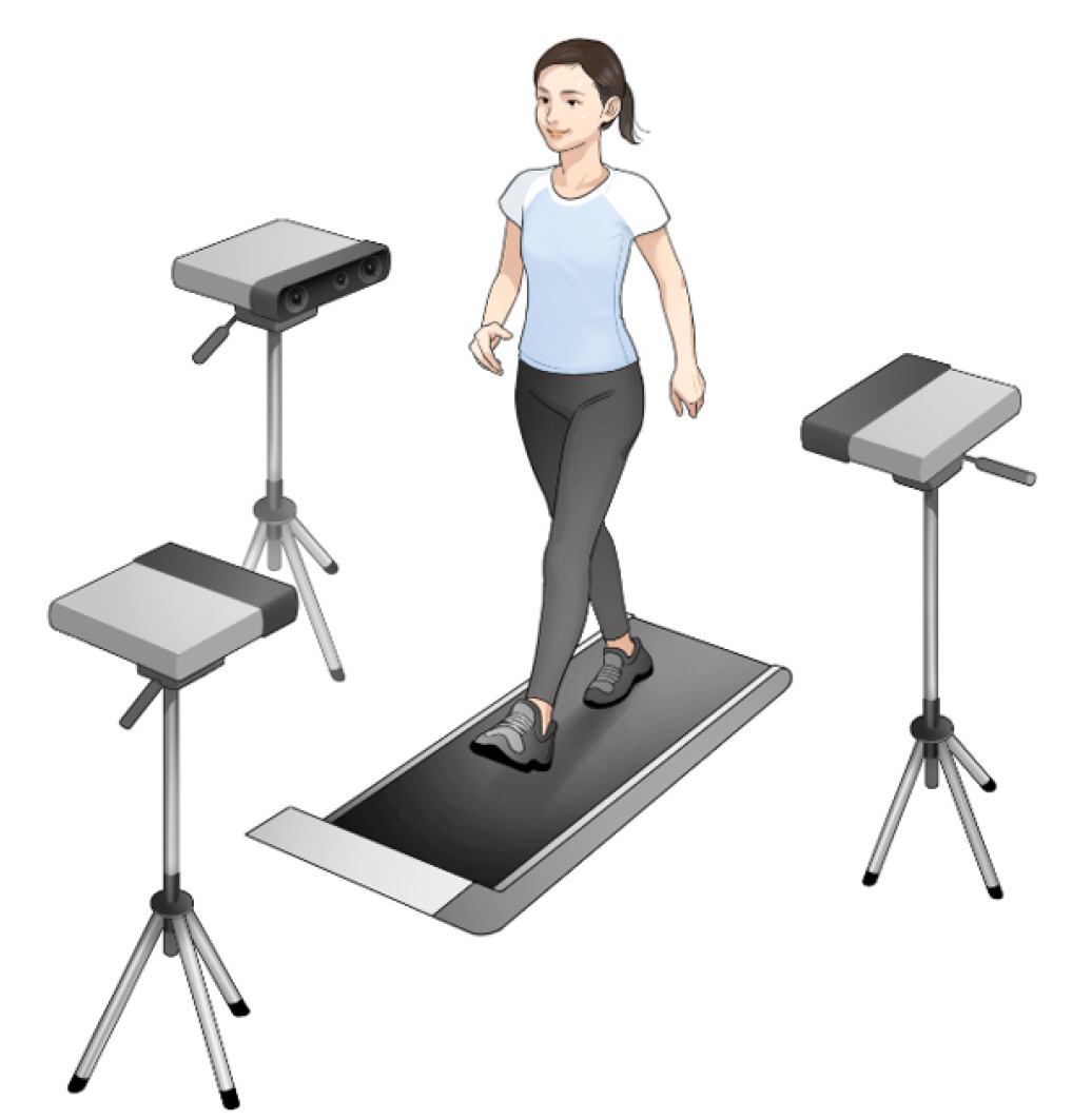
Experimental setup for motion tracking. The frontal depth sensor pointed directly toward the treadmill for the full-frontal plane view, and the other sensors pointed to the sides (left and right arm) orthogonal to the frontal camera.
Motion during the experiment was captured at 30 Hz, and data acquisition proceeded using markerless motion capture software (iPi Motion Capture, LLC) (Fig. 2A). Inverse dynamics were computed from the kinematic measurement values (ROM, position, velocity, and acceleration of elbow and shoulder) of the depth sensor data. The elbow was considered to be set at 2 degrees of freedom (DOF), its flexion/extension and pronation/supination angles were measured, and moments were calculated for sagittal and axial planes, respectively. The shoulder joint was treated as a 3-DOF joint; its flexion/extension, abduction/adduction, and external rotation/internal rotation angles were measured; and moments were calculated for sagittal, coronal, and axial planes, respectively. When the three depth sensors started body tracking, their respective PCs independently sent data to the main computer that collected data for synchronization.
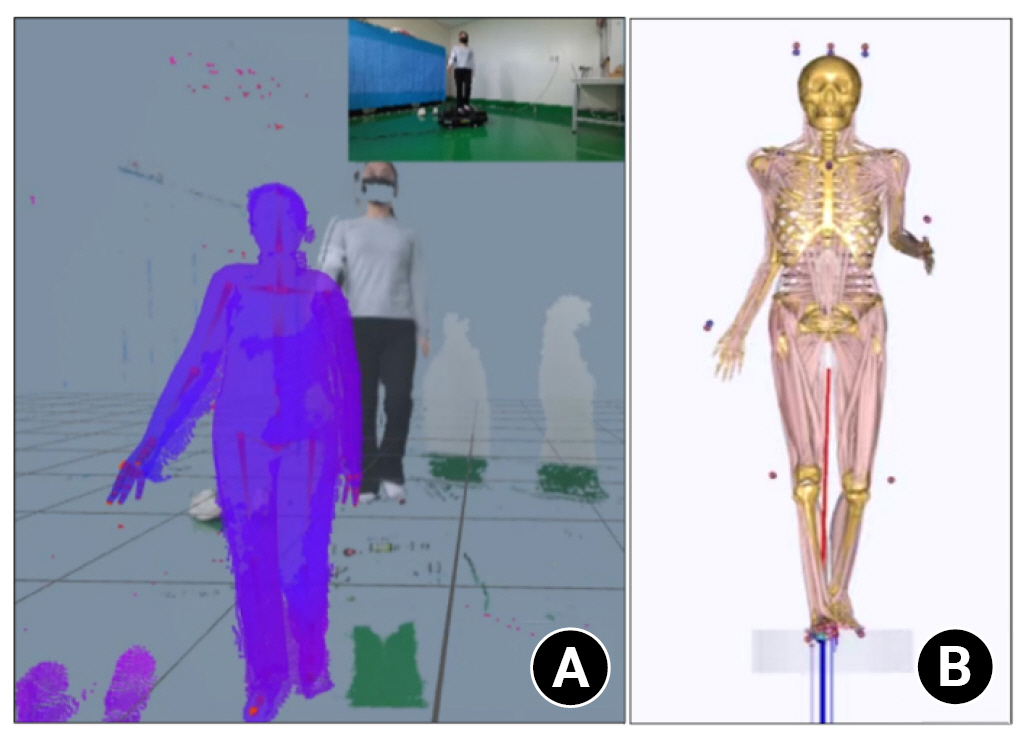
Inputting the location data for computational modeling. (A) The motion during the experiment was captured at 30 Hz, and data acquisition proceeded using the markerless motion capture software (iPi Motion Capture, LLC). (B) The specific X-Y-Z locations obtained from the motion capture session were used as input to the musculoskeletal model in AnyBody Modeling System software (AnyBody Technology, version 7.3.0).
Experimental Protocol
Subjects were instructed before the start of the experiment to warm up by walking at a constant speed controlled by the treadmill (walking, 1.11 m/sec) for 60 seconds to become familiar with the apparatus. The constant speed for walking was selected based on a reference gait dataset for a 20- to 39-year-old age group [13]. The reference gait patterns of the speed (walking, 30 seconds per trial) were recorded by depth-censored cameras.
Computational Musculoskeletal Modeling
The specific X-Y-Z locations obtained from the motion capture session were used as input to the musculoskeletal model in the AnyBody Modeling System software (ver. 7.3.0, AnyBody Technology). A global axis specified the environmental factor of gravity (−9.8 m/sec2 in the superior–inferior direction). The upper body portion of the full-body model from the AnyBody Managed Model Repository (ver. 2.3.0) was used. The model consists of multiple bones comprising the pelvis, trunk, neck, and arms. The arm consists of several joints including three spherical joints (sternoclavicular, acromioclavicular, and glenohumeral), three revolute joints (elbow and two in the wrist), and pronation/supination of the forearm. The model also includes lumbar, thoracic, and cervical spine regions and contains multiple muscle fascicles of upper body muscles (Fig. 2B). The generic model was scaled to each subject using anthropomorphic data. The muscle groups were sectioned into force vectors connected at two points in the body to represent the origin and insertion points of the muscle. Moreover, model parameter identification and inverse dynamic analysis were conducted following a previously validated study [14]. Inverse dynamics is a concept used primarily in biomechanics, robotics, and control engineering to analyze and understand the forces and torques involved in the motion of a system. It refers to the process of working backward from the desired motion or trajectory of a system to determine the required forces and torques at each joint or point of interaction. In contrast to forward dynamics, in which forces and torques are used as inputs to calculate the motion of the system, inverse dynamics starts with the motion (position, velocity, and acceleration) and calculates the forces and torques required to achieve that motion.
Data Analysis
Data analysis was completed using MATLAB. The data were segmented into trials, where segmented gait patterns were normalized to the gait cycle. Seven gait cycles in the middle of each 30 seconds recording were selected and averaged for data analysis. A gait cycle was defined as the movement from touchdown of the heel of the reference foot on the ground to the endpoint of the terminal swing of the same foot (Fig. 3B).
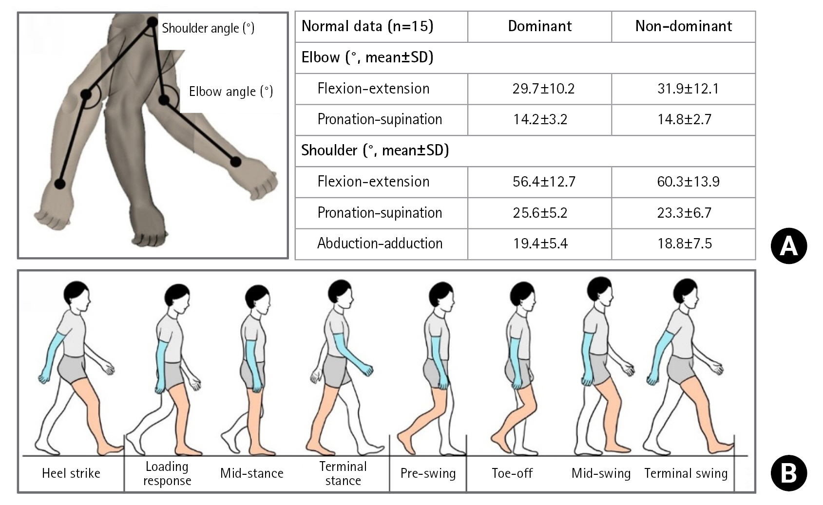
(A) Normative data for arm swing in a gait cycle. (B) A gait cycle was defined as the period from the strike of the heel of the reference foot with the ground to the endpoint of the terminal swing of the same foot. SD: standard deviation.
All postacquisition data processing was performed in Python 3.7.4. After averaging the normalized kinematic gait patterns of the 10 sampled steps, the ROM was computed in terms of maximum and minimum joint angles for each trial. The mean joint moment of each time frame in each joint was calculated in Newton meters (Nm).
Statistical Analysis
Statistical analysis was performed under the supervision of a biostatistician. The Kolmogorov-Smirnov test was used for normality distribution for all datasets. All descriptive and quantitative analyses were conducted using SPSS ver. 22.0 (IBM SPSS Corp.).
RESULTS
ROM during a Gait Cycle
The mean ROM of the dominant elbow during a gait cycle was 29.7°±10.2° and 14.2°±3.2° in flexion–extension and pronation–supination, respectively (Fig. 3A). The mean ROM of the dominant of the dominant elbow during a gait was 56.4°±12.7°, 25.6°±5.2°, and 19.8°±4.6° in flexion–extension, rotation, and abduction–adduction, respectively.
Joint Moment during a Gait Cycle
The mean joint moment (in Nm) of the dominant elbow during a gait cycle was 33.5±9.2 and 1.2±0.4 Nm in flexion–extension and pronation–supination, respectively (Fig. 3A). The mean joint moment of the dominant shoulder during a gait cycle was 91.3±22.6, 11.0±4.3, and 25.5±12.0 Nm in flexion–extension, rotation, and abduction–adduction, respectively.
DISCUSSION
Although the elbow joint is not weight-bearing, the motion of the shoulder creates a joint moment by gravitational force on the weight of the forearm. The mean joint moment (in Nm) of the dominant elbow during a gait cycle was 33.5±9.2 and 1.2±0.4 Nm in flexion–extension and pronation–supination, respectively. This demonstrates a definite load on the elbow during daily activity, with increased load when carrying an object. In the same regard, the shoulder joint is also load bearing. In our results, the mean joint moment of the dominant shoulder during a gait cycle was 91.3±22.6, 11.0±4.3, and 25.5±12.0 Nm in flexion–extension, rotation, and abduction–adduction, respectively.
The elbow load can be increased greatly during sports activities (e.g., weightlifting, gymnastics, and any kind of racket sport). Although the knee and hip joints are likely to experience relatively unidirectional and consistent loads created by body weight, the shoulder and elbow joints receive various weight forces according to objects held in the hand or hung on the forearm and by type of activity and the various directional forces. The muscles of the shoulder and elbow (deltoid, rotator cuff, pectoralis, brachialis, biceps, and triceps) also create joint moments in the joints. Gravity also can exert distraction force on the shoulder and elbow in their neutral positions. However, the computational simulation applied the joint moment against gravity once the muscles were contracted.
Methodologically, the present study was the first of arm motion tracking using a markerless motion capture camera (Azure Kinect). Markerless motion capture has been highlighted as a promising solution to overcome the weakness of optical motion capture systems that require reflective markers. The Microsoft Kinect is a low-cost, portable device containing a body tracking system that can measure three-dimensional joint positions. The Kinect body tracking system has been validated in gait and posture studies and in clinical settings [15-17]. In our study, dynamic gait motion capture was successfully recorded during treadmill walking that was validated in a previous study [18]. The present study calculated the ROM and joint moment of the shoulder and elbow joints during arm swing motion for the first time in the published literature.
This is the first study to build a computational musculoskeletal model using a markerless motion tracking sensor. Dynamic kinematics can be used to measure and analyze arm motion with computational modeling. The findings of the study can be a reference for further related studies. However, this study controlled the velocity of the gait, which can introduce bias and does not fully reflect the natural arm swing motion in daily gait.
CONCLUSIONS
The present study demonstrated that the elbow bears a dynamic load created by gravity and muscle contracture during dynamic arm swing motion.
Notes
Author contributions
Conceptualization: GHJ, JMK. Data curation: BK, EK, JMK. Formal Analysis: BK. Funding acquisition: IHJ. Methodology: BK, GHJ, EK, JMK. Project administration: IHJ. Resources: IHJ.
Software: EK. Supervision: IHJ. Validation: BK, GHJ, EK, IHJ. Visualization: JMK. Writing – original draft: JMK. Writing – review & editing: GHJ, EK, IHJ.
Conflict of interest
None.
Funding
This work was supported by a National Research Foundation of Korea (NRF) grant funded by the Korean government (MSIT) (No. NRF-2021R1G1A1095581). This paper was supported by an EMBRI grant (2021-EMBRISN0008) from Eulji University. This study was supported by Eulji University in 2021.
Data availability
Contact the corresponding author for data availability.
Acknowledgments
None.